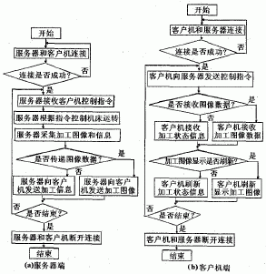
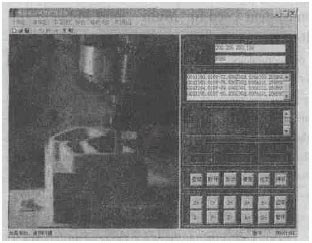
2.3 Network Control System Software Design A friendly human-machine interface is indispensable for any control system. The interface design of this system adopts the separation view technology in Windows programming, and divides the man-machine interface of the numerical control system into two sub-windows. The left window is the image display window, which realizes the image monitoring of the machine tool processing; the right window is the network control window, which realizes the functions of network connection and disconnection, processing code editing and transmission, machine tool processing status parameter display, machine tool online network debugging and so on. The key to software design is the network transmission of data. In order to ensure the timely delivery of data, multi-threading technology is adopted in the software design, and a thread is specially established to carry out network transmission of the collected machine tool data. The flow chart of the system is shown in Figure 5. After the NC code is edited on the client, it can be passed to the server at one time. The server saves the NC code to the memory and then executes the NC code. The transfer of control instructions can be passed from the client to the server at any time, and the server executes immediately upon receipt of the instruction. The transfer of machine image and state parameters is more complicated. On the server, the CNC system collects the processed image in real time through the CCD camera, uses the timer to save the image as a bitmap file in each cycle, and then transfers the bitmap file to the client through the network. The client receives each bit. After the file is displayed, the timer is refreshed and displayed in the image display window every cycle to maintain the continuity of the processed image. At the same time, the numerical control system on the server collects the machine state parameters in real time, and uses the timer to transmit data in a certain format to the client every cycle. The client analyzes the data after receiving it, and then uses the timer to perform the state parameters in one cycle. Update the display. In order to avoid the confusion of bitmap data and parameter data during transmission, the interrupt method is adopted on the server side, the parameter data is interrupted when the image data is transferred, and the parameter data is transmitted after the image data is transmitted, so that the solution is well solved. The contradiction of the occupied channel in the data transfer process. Figure 5 Network Control System Software Flow Chart There is a certain hysteresis in the image display and parameter update during the running of the software, which has a certain relationship with the speed of network transmission and the amount of data. 3, network control system demonstration Figure 6 shows the demonstration of network monitoring of machine tool processing in the developed network control system. It can be seen from the experiment that the real-time transmission of control commands and status data is good, which can meet the needs of actual control; the image display in the processing state has a slower refresh rate, a slightly lower real-time performance, and the image display has jumpability, and the image needs to be further improved. The fluency of the display. Figure 6 Network control system remote monitoring demonstration interface Previous page next page Hubei Chengze Diamod Products Co., Ltd. , https://www.ryomaltools.com
