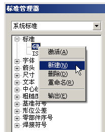
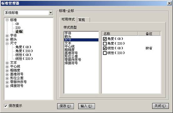
At present, the domestic mechanical design is basically the result of the final design of the two-dimensional engineering drawings. If you use 2D > CAD, you don't need to say more, it's just a drawing. With 3D > CAD, only 3D models are obviously not enough: a), manufacturing and processing. In the domestic situation, it is obviously impossible to completely process without drawings. As long as it is not CNC machining, it is necessary to have engineering drawings. The 3D model can be used as an effective aid, but it is impossible to machine parts only by means of 3D models; b), inspection. Similarly, the inspection is also inseparable from the two-dimensional drawings, and the inspection data including the dimensions, tolerances, geometric tolerances, roughness, etc. are more clearly expressed on the two-dimensional drawings; c), assembly. The 3D model can visually represent the state of the assembly, but the 2D engineering drawing has its special advantages in terms of expressing the internal structure, expressing the assembly relationship, some special indications, and generating the parts list. d), archive. After the product design is completed, to ensure the frozen state of the product, the 3D model is software dependent, and the software is always changing in the upgrade, so the product status is difficult to control, the version control of the product is also very error-prone, and the 2D drawing will not Have these concerns. 5) Data exchange. If the two parties to the exchange use different software, the conversion loss of the two-dimensional data is much less than that of the three-dimensional one. It can be seen that the two-dimensional engineering drawing plays an important role in practical applications. The power of the 3D module has greatly accelerated our design and greatly improved the quality of the design, but the final output still depends on the 2D engineering drawing. The 3D function of 3D software is of course stronger, but in actual design, the proportion of particularly complicated parts is very small, and the engineering drawings are produced for each part of each part, so the drawing The powerful software of the module is the real practical software. Formulating standards There are multiple sets of standards in the system standard. The standardization department can define multiple sets of standards to be placed here, and the designer can select the appropriate standard plot. There can only be one current standard, which means that one drawing can only have one standard. There are two sets of default system standards in the software: >GB and >ISO (can be changed to delete). Because the standards stipulate a wide range of content, and each company in each industry has different understandings of standards because of its own characteristics, these two standards can only be used as a reference. We started to create a new standard, first select the system standard option from the drop-down list, and the standardization work should be done under the system standard. New standard "Right→New" on the "Standard" root node will generate an empty standard. The empty standard has only one name and does not contain any style. Right-click on the existing standard name to create the standard. The template produces a copy standard, the copy standard is exactly the same as the original standard, and a small number of changes can be used to generate a new standard. Right-click on the >GB to create a new standard and change the name to "Enterprise". Right click on the "Enterprise Standard" to activate it. The standard name font is bolded after activation. The default current standard when creating a new drawing is the activation standard in the system standard. Subsequent editing of the standard is facilitated after activation. Definition standard Click on the enterprise logo, and the icon in the display area on the right appears: The style type is the style category name, which corresponds to the one in the tree list on the left. Taking "size" as an example, the list on the left lists all the style names contained in the size, and the display area on the right lists more detailed content: the check mark before the name indicates that the style belongs to the currently selected standard ( That is, "enterprise", you can select or select a standard by clicking on the style; the "default" in the comment indicates that the style is the default style of this standard. A standard can contain multiple size styles, but there can only be one default style for the size. The default style cannot be selected. You can set the other styles to default first (right click on the name → set to default) Then choose. Select "Enterprise" and click the "General" tab in the display area to set some basic parameters of the standard: line width series value and text height series value. After the setting is completed, under this standard, the line width and the setting of the font style can only be selected from this series, so as to achieve the standardization effect. When the "Enterprise Standard" is newly created, it is a copy of " >GB", which is exactly the same as " >GB". Generally speaking, the standard line width series value and the text height series value based on the national standard are the same, so a slight change can be used here to meet the requirements; if you start to create a new empty standard, the series value here is one. One added. Next page Fulcrum Mini Electric Hoist,Mini Electric Wire Rope Hoist,Mini Electric Rope Hoist,Mini Electric Cable Hoist Guangdong Gongyou Lift Slings Machinery CO.,LTD , https://www.workmateslift.com

Application of Solid3000 V7.0 multi-standard system (Figure)
First, the importance of engineering drawings in the machinery industry