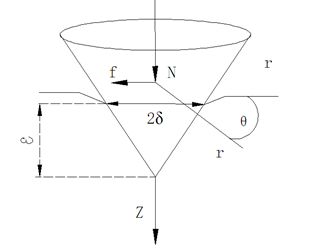
Abstract: This paper mainly expounds the principle of mortar line cutting, tension control system, mortar performance and recycling, and points out the shortcomings of the research, in order to promote the research and development of mortar wire cutting technology and guide the actual production. introduction At present, the main material of solar photovoltaic cells is silicon-based materials, and silicon-based photovoltaic cells account for more than 85% of the world's photovoltaic cells. As the front-end product of the solar photovoltaic industry, crystalline silicon wafers occupy an important position in the entire photovoltaic industry chain. Multi-wire cutting is divided into mortar wire cutting and diamond wire cutting. The former is the main way of silicon wafer production. It uses a mixture of silicon carbide (SiC) and cutting fluid (PEG) to form a mortar, in steel wire and silicon. Under the pressure of the rod, the surface of the silicon rod is plastically deformed and cracked to form a cut [1]. With the development of the photovoltaic industry, the quality of silicon wafers is higher, and the research on wire cutting will be deeper and deeper. This paper mainly elaborates on the model and principle of mortar line cutting, the type and development direction of tension control system, the factors affecting the performance of mortar, and the control measures; the recovery and reuse of mortar, etc., in order to promote the in-depth study of mortar wire cutting technology. Guide actual production. 1 cutting mechanism research In the process of cutting the silicon rod by mortar line, the silicon carbide particles perform the "rolling-indentation" between the silicon rod and the steel wire to realize the material removal [2]. Shu Jiqian et al [3] elaborated on the cutting mechanism, including single particle rolling-indentation model, multi-particle indentation effect model and elastic-fluid effect model. The cutting force of the single particle model is simulated by Yu et al. [4], as shown in Fig. 1. The formula for calculating the normal cutting force N is obtained from the graph. (1) where: ε is the maximum cutting depth; a is the contact length; Ï… is the Poisson's ratio; E is the Young's modulus; ζ = z / a, Ï = r / a; μ is the friction coefficient, other Is a constant. The tangential cutting force can be calculated by the normal phase cutting force: Figure 1 Schematic diagram of the force of single-particle silicon carbide At the same time, using finite element software to simulate the influence of different cutting line speed and feed on stress and strain, it is concluded that the maximum stress and maximum strain in cutting feed and cutting zone are inversely proportional; cutting line speed and maximum stress and maximum strain in cutting zone Both are proportional relationships. Corner Paint Pad,Paint Pad Pro,Paint Pad For Edges,Corner Pad Plastic Angled Decking Ningbo Beilun Gelei Plastic Parts Co.,Ltd , https://www.paintwelltools.com Summary of research on mortar wire cutting technology (1)

 (2)
(2)  (3)
(3)  (4) where: β = cos θ dimensionless coefficient.
Summary of research on mortar wire cutting technology
Polaris Solar Photovoltaic Network
Keywords: silicon wafer wafer cutting mortar wire cutting
|<123456>>