You can use a series of commands in combination, and hope to help newcomers. First look at the final result: Start the tutorial steps below: First, create a polygon (my is 24 sides) Third, copy the circle, the center of the circle is placed at the midpoint of the edge, as shown in the figure: Fourth, the overall copy, spare. as the picture shows: Fifth, establish a yellow area. 7. Copy the finished product to the spare polygon. Eight, mirror red line, connect Nine, establish a domain Ten, switch views, stretch, move Eleven, draw two spheres Thirteen, switch the view, transfer the finished product to the standby Fifteen, with the auxiliary line as the midpoint, array 16. Create a map area and mirror one Seventeen, rotated 90 degrees Nineteen, rotated 90 degrees, as shown: Twenty, with base point copy, as shown: Twenty-one, rotating two areas, as shown in the figure: Twenty-two, the extra lines are classified as the same invisible layer, coloring, OK! Twenty-three, plus a certain material.
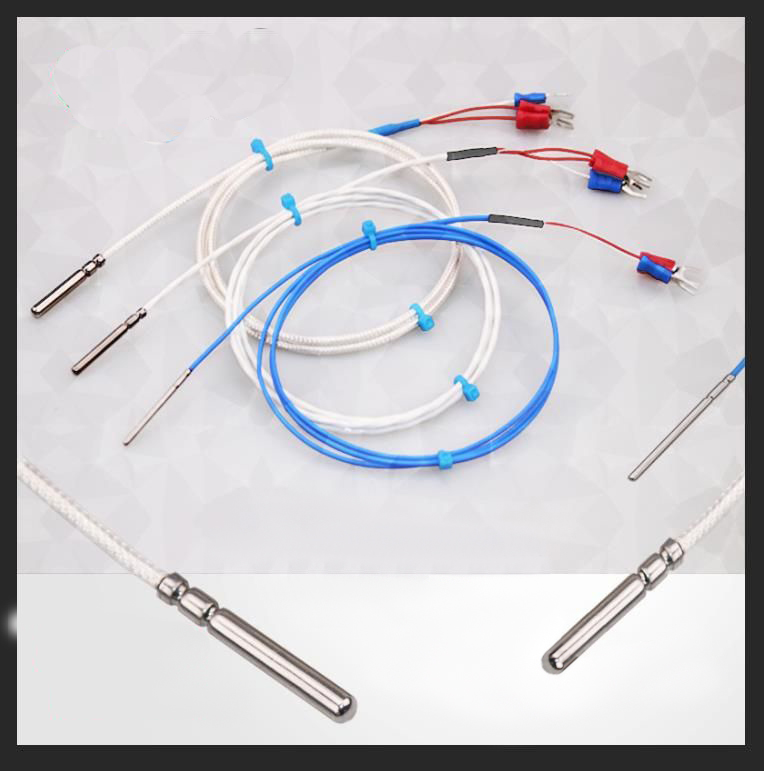
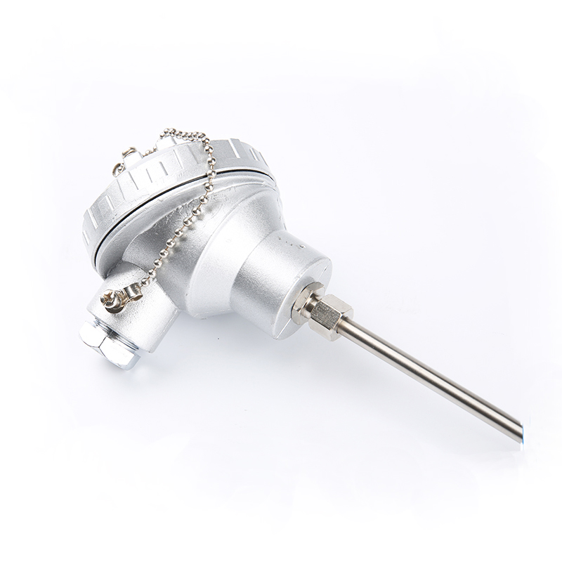
Temperature transmitter is an instrument that converts a temperature variable into a transmittable standardized output signal. Temperature transmitters convert physical measurement signals or ordinary electrical signals into standard electrical signal output or devices that can output in the form of communication protocols. A temperature transmitter is an instrument that converts temperature variables into a transmittable standardized output signal, and is mainly used for the measurement and control of temperature parameters in industrial processes. The current transmitter is to convert the AC current of the main circuit under test into a constant current loop standard signal, which is continuously sent to the receiving device
Features of the temperature transmitter:
1. Two-wire output DC4-20mA current signal, strong anti-interference ability;
2. Save the cost of compensation wire and installation of temperature transmitter;
3. Large measurement range;
4. Automatic compensation of cold junction temperature, non-linear correction circuit.
Applications of temperature transmitters:
Usually used with display instruments, recording instruments, electronic computers, etc., widely used in petroleum, chemical, chemical fiber; textile, rubber, building materials; electric power, metallurgy, medicine; food and other industrial fields for on-site temperature measurement process control; especially suitable for computer measurement and control The system can also be used in conjunction with the instrument.
Temperature transmitters make it possible to send a scaleable (4 to 20) mA signal from a Temperature Sensor to a control device without investing in long, expensive runs of thermocouple or RTD wire.
Pyromation carries programmable RTD and thermocouple temperature transmitters that can be mounted in the temperature sensor assembly connection head, or surface mounted using a DIN rail mounting clip. Some units offer a visual digital display that shows the current measured value. All are PC programmable and convert various signals into a scaleable (4 to 20) mA analog output signal. We also carry transmitters programmable with Hart® protocol for various signal inputs. Depending on type, some of Pyromation`s thermocouple and RTD temperature transmitters are UL recognized components and/or FM and CSA approved, including styles that are intrinsically safe and approved for use in hazardous locations.
Pyromation temperature transmitters are used in many demanding industries including Pharmaceuticals, Oil & Gas, Power Generation, Chemical, PetroChemical, and Food and Dairy.
Temperature Transmitter,Temp Transmitter,Thermocouple Transmitter,Rtd Temperature Transmitter Wuxi Winsun Automation Instrument Co., Ltd , https://www.winsunwx.com
Effect 1
Effect 2
figure 1
Second, draw a circle with the center of one side as the center, as shown in the figure:
figure 2
image 3
Figure 4
Figure 5
Sixth, rotating yellow area
Image 6
Figure 7
Figure 8
Figure 9
Figure 10
Figure 11
Twelve, ask for two difference sets
Figure 12
Figure 13
Fourteen, draw the ball, and draw as shown in the auxiliary line
Figure 14
Figure 15
Figure 16
Figure 17
Eighteen, with the base point copy, as shown:
Figure 18
Figure 19
Figure 20
Figure 21
Figure 22
Figure 23
Figure 24 

AutoCAD example tutorial: the whole process of bearing modeling
I started to paint a bearing for the old farmer, which shocked me for a long time! I drew one in the morning, but the tray (bead hoop) is not an arc! I observed it carefully in the afternoon and built the model.