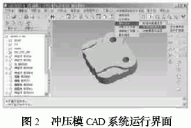
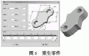
The computer-aided design software Pro/E is a parametric solid modeling software that not only generates real geometric shapes, but also performs accurate model analysis, motion analysis, and interference checking. Pro/E's parametric feature modeling technology greatly reduces the drawing workload of designers, improves the efficiency and quality of product design, and develops CAD-based systems for stamping dies using Pro/E's corresponding development tools and techniques. The realization of part design, assembly design, processing design, etc., at the same time, thereby shortening the manufacturing cycle of the mold and improving the quality of the product. Second, the composition of the stamping die CAD system The stamping die can be divided into punching die, bending die, drawing die, forming die, etc. according to the nature of the process. No matter what kind of die, basically, the upper and lower die body, the guiding device, the pressing device, the positioning device, etc. are required, so The stamping die CAD system is a convenient and easy-to-use design system integrating stamping die design system, stamping die machining simulation and stamping die work simulation. The system structure is shown in Figure 1. Figure 2 shows an interface of the system running in a Pro/E environment. Third, the application of Pro/E parameterization technology in stamping die CAD system Pro/E software provides users with a variety of parametric design development tools while providing powerful design, analysis, and manufacturing capabilities. The stamping die contains a large number of standard and common parts, as well as some special parts. When designing and applying the parts, apply secondary development tools of Pro/E, such as Family Table, Pro/ Pro2gram, Developed by Pro/Toolkit, etc., it can be designed efficiently and quickly. 3. 1 Pro/E based parametric design development steps Parametric design and development based on Pro/E generally has three steps: 1 Using Pro/E's solid modeling and parameter-driven functions to model parts; 2 Setting parameters and setting relationships between parameters. Thus to meet the needs of parameter-driven - using the relationship drop-down menu in the tool menu; 3 using the tools provided by Pro / E for parametric design and development. 3. 2 parametric design development and application (1) Application of family table technology In the design of parts, if some parts are the same structure, but the size is different, then these parts do not have to be built individually. You can create a parent part, define the parameters of each control part shape, and change the value of each parameter at design time. To get the required derivatives, to create a series of parts, the collection of these parts is called the family table. Since the structural shape and size of the standard parts have been standardized, the standard parts library in the mold design system is developed by the family table technology, so that the design purpose can be conveniently and quickly achieved. FIG. 3 is an interface for designing parts by using the family table. There are two issues to be aware of when building a parent part: 1 The parent part generally adopts the largest standard part of the same type of standard parts. 2 The parent part shall contain all the features of the same type of standard parts. (2) Application of Pro/Program technology The development of 3D parametric design using program control model mainly includes 3 items: acquisition and display of parameter objects; update and modification of parameter objects; regeneration of models. Figures 5 and 6 are an example of development using the method described. Figure 5 shows the part model template. You can change the size of one of the parameters to regenerate the part. You can also select the parameter series value from the list to regenerate the part. Figure 6 shows the situation of regenerating the part after changing the thickness to 50 min. Fourth, the conclusion Electrophoresis aluminum profiles Aluminium Profile,Aluminium Extrusion,Aluminium Extrusion Profile Shandong Huajian Aluminium Group Co., Ltd. , http://www.sdaluminumprofiles.com I. Introduction 


Pro/Program is a file that records the model building process. It records the steps and conditions of the model generation, including the model information of all feature creation processes, parameters, dimensions and relationships. The system will write the information of each feature. In the program, the user can change the features of the part by editing a very simple programming language. The "program" can be used to control the presence or absence of features in the part, the size and size of the parts in the assembly, the number of parts, etc., so that it is convenient to design a series of different products. Due to the similar structural shape and size of the common parts, the program technology is used to develop the common parts library in the mold design system.
The Pro/Program program consists of five partial sequences: program title, input prompt information, input relationship, added features (or parts), and quality characteristics. The user can enter the prompt information section (INPUT and END INPUT) as needed. Add a modifiable parameter name.
(3) Parametric design technology application based on Pro/Toolkit development
There are two development methods based on Pro/Toolkit 3D parametric design: 1 Application feature description method uses the underlying functions provided by Pro/Toolkit to complete feature modeling, and establish man-machine dialog box to realize 3D parametric design. It is cumbersome. It is very difficult to use a program to generate a 3D model for a product with complex shapes. 2 A combination of 3D model and program control is used. The basic process is to generate a 3D model interactively in a Pro/E environment. Based on the 3D model of the created part, a set of design parameters that can fully control the shape and size of the 3D model is established according to the design requirements of the part. The parameterization program programs the design parameters of the part to realize the retrieval and modification of the design parameters and the function of generating a new three-dimensional model according to the new parameter values. The flow is shown in Figure 4. This method can generate a product model with complex shapes, and the programming is relatively simple and is adopted by many developers. 


Parametric design is a topic that CAD technology puts forward in practical applications. Parametric design can not only develop a dedicated product design system, but also parameterize the product design, thus freeing designers from a large number of heavy and trivial design work. Come out, easy to achieve part design, mold design, assembly design, processing design, etc., speed up the mold design process, shorten the design, manufacturing cycle, enhance new product development capabilities, enhance market competitiveness.