What kinds of solutions should be used to adjust the valve fault? Which type of solution should be used to maintain the position?
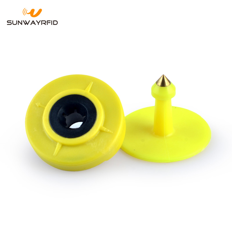
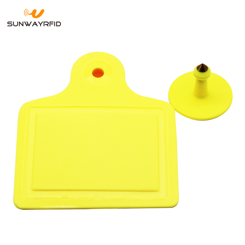
SunwayRFID provides the rfid ear tags are in TPU material, standard in ISO11784/785 (FDX, HDX). TPU material is for animal, no worry about skin sensibility.
RFID ear tags can work in -25℃ to 70℃, reading from 5cm to 60cm, relative with the reader.
In yellow, no printing. Custom color and logo laser printing available too.
RFID ear tags popular using livestock tracking and management, like cow, sheep, pig and so on.
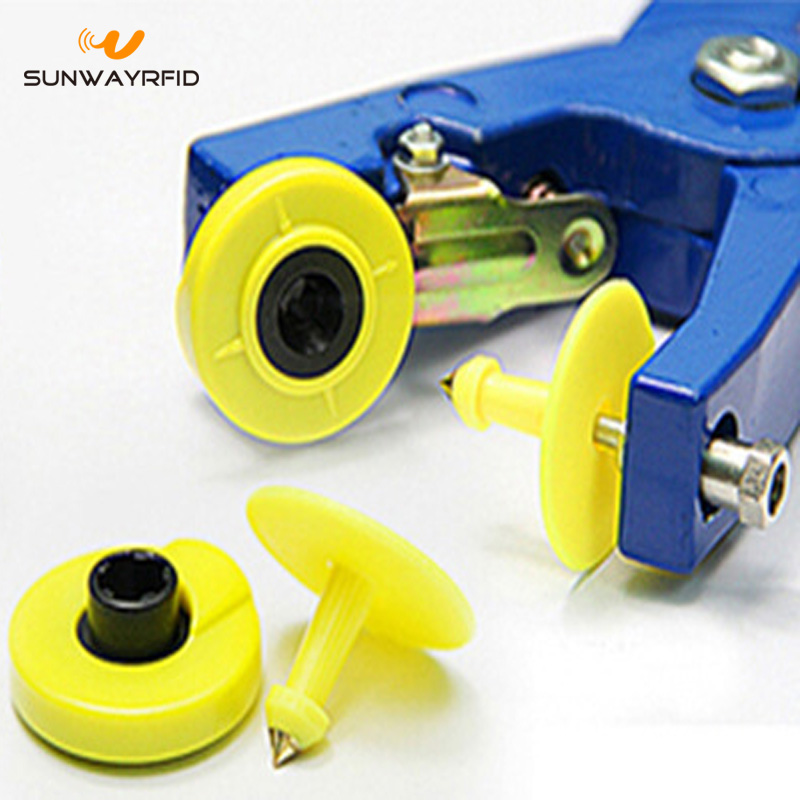
Using a pliers and easy to put the rfid ear tags on the ear.
Animal RFID Tag can be embedded 125Khz chips like Tk4100, EM4200, T5577, EME44305 and Hitag etc.
Besides, SunwayRFID also provides Silicone RFID Wristbands, RFID Bracelet, elastic wristbands, Fabric Wristbands, pvc wristbands, RFID Keychain, rfid tag and rfid cards, one-shop can meet all your need about RFID.
Price, customer service, and quality always at our first place.
The role of the regulating valve in process control is well known. In many control processes, the regulating valve is required to be in a certain position during the fault to protect the process from accidents, which requires the regulating valve to fail in design— Safe three-break (off gas, power off, break signal) protection measures. For the electric control valve, it is relatively simple. When the signal is broken, it can stay at any position of full opening, full closing and holding according to the setting of the control module. When the power is off, it naturally stays at the fault position, or Electric actuators with a reset device can also operate the valve position to full or full closing.
For pneumatic control valves, the situation is more complicated, so we mainly discuss the three-stop method of pneumatic control valve. Generally speaking, when selecting a pneumatic diaphragm regulating valve, we must first determine whether the air is selected or closed. This is the protection position when the control valve is cut off. If the valve is open when the process requires air shutoff, then the normally open (closed) ) adjust the valve, otherwise choose the normally closed (air open) type regulating valve. This is only a superficial solution. If the process requires three-break protection of gas-breaking, power-off, and off-signal, the regulating valve needs to be equipped with some accessories to form a protection system to achieve control requirements. These accessories mainly include retaining valves and solenoid valves. , gas tanks, etc. The following are two types of retention schemes for single-acting pneumatic diaphragm regulators and double-acting pneumatic regulators.
1. Pneumatic diaphragm regulating valve solution (regulating valve with electric-gas valve positioner)
The program mainly consists of a pneumatic regulating valve, an electric-gas valve positioner, a power loss (signal) comparator, a single electronically controlled electromagnetic reversing valve, a pneumatic retaining valve, and a valve position signal returning device. Its working principle is as follows:
1. Gas source: When the control system air source is faulty (gas loss), the pneumatic retaining valve automatically closes to lock the output signal pressure of the positioner in the membrane chamber of the pneumatic control valve, and the output signal pressure and the reaction force generated by the control valve spring Phase balanced, the valve position of the pneumatic control valve remains in the fault position. The retaining valve should be set to start slightly below the minimum value of the air supply.
2, power off: When the control system power failure (power loss), the power loss (signal) comparator control single electronically controlled electromagnetic reversing valve output voltage disappears, single electronically controlled electromagnetic reversing valve power loss, single electronically controlled electromagnetic The spool valve in the reversing valve slides under the action of the return spring, the solenoid valve is reversed, the diaphragm pressure of the pneumatic retaining valve is emptied, the pneumatic retaining valve is closed, and the output signal pressure of the positioner is locked to the pneumatic control valve. In the membrane chamber, the output signal pressure is balanced with the reaction force generated by the control valve spring, and the valve position of the pneumatic control valve is maintained at the fault position.
3. Break signal: When the control system signal is faulty (missing signal), after the power failure (signal) comparator detects, the voltage signal of the single electronically controlled electromagnetic reversing valve is broken, and the single electronically controlled electromagnetic reversing valve is de-energized. The slide valve in the single electronically controlled electromagnetic reversing valve slides under the action of the return spring, the solenoid valve is reversed, the diaphragm pressure of the pneumatic retaining valve is emptied, the pneumatic retaining valve is closed, and the output signal pressure of the positioner is locked. In the membrane chamber of the pneumatic control valve, the output signal pressure is balanced with the reaction force generated by the control valve spring, and the valve position of the pneumatic control valve is maintained at the fault position.
The position feedback signal is given by the position signal return.
The advantage of this scheme: When the "three-break" protection is activated, the system reacts quickly and moves quickly. The overall cost is relatively cheap.
Disadvantages of this solution: The solenoid valve is energized for a long time, which affects the service life. There are many accessories, and the installation and debugging are more complicated. The valve position feedback needs to be equipped with a valve position signal returner. In the case of a hand wheel, it is more complicated.
Second, double-acting pneumatic regulating valve solution (regulating valve with electric-gas valve positioner)
The program is mainly composed of a control valve, a gas-controlled reversing valve, a positioner, a self-locking valve, a check valve, a pressure reducing valve, a gas storage tank and the like. Its working principle is as follows:
When the control system air source is faulty (gas loss), the self-locking valve (which acts in the opposite way to the retaining valve) is automatically opened, and the control air supply of the pneumatically controlled reversing valve is cancelled. The spool of the pneumatically controlled reversing valve is in the spring. Under the action of resetting, one of the two pneumatically controlled reversing valves, the other intake, the check valve is closed, the gas source is supplied to the valve by the gas source stored in the gas storage tank, thereby realizing the valve Off or fully open. Fully or fully open conversion can be achieved by adjusting the connection of the pneumatically controlled directional control valve.
If you want to achieve valve retention, install a pneumatic retaining valve and change the pipeline connection, use the self-locking valve to directly control the retaining valve, and cancel the pneumatic control reversing valve, check valve, and gas storage tank.
In order to achieve a gas source, the valve can be operated several times, and the following scheme can be used.
The program consists of a gas storage tank, a check valve, a lock valve, a shut-off valve and the like. Its working principle is as follows:
When the air source is faulty (gas loss), the check valve is closed, the lock valve is out of gas, the slide valve of the lock valve is reset by the action of the spring, the gas path is reversed, the air supply line of the system is disconnected, and the gas storage is turned on. The gas tank pipeline supplies gas from the gas storage tank to the valve to ensure that the valve has several movements for continuous control purposes. Since the capacity of the gas storage tank is limited, and the pressure of the gas source in the gas storage tank is continuously decreasing as the valve moves, the gas storage tank cannot be used for gas supply for a long time. The capacity of the gas storage tank used in this scheme should be larger than the capacity of the general protection gas storage tank. When the program is shut off, the number of valve actions is related to the capacity of the gas storage tank.
For the retaining scheme of the pneumatic diaphragm regulating valve, there is also a reference: a series of retaining valve and a two-position three-way solenoid valve between the positioner and the actuator, and a retaining valve to retain the position when the gas is cut off. When the signal is broken, the solenoid valve is used to maintain the position. However, the solenoid valve must be interlocked with the positioner (set in the control program), that is, the positioner has a signal, the solenoid valve must have electricity, and once the positioner loses the signal, The solenoid valve must be powered off immediately.
Http://news.chinawj.com.cn Editor: (Hardware Business Network Information Center) http://news.chinawj.com.cn


Animal rfid tag can be embedded 13.56MHZ chips like Ntag213, NTAG215, NTAG216, Mifare Classic, Desfire EV2/EV2, Plus X, Plus SE, ICODE, Ultralight, TI 2084, Topaz512, and F08 etc.
Animal rfid tag can be embedded 860MHZ-960MHZ chips like Alien H3, Alien H4, U-Code Gen2 and Impinj M4/M5 etc.
RFID Ear Tag
RFID Ear Tag,RFID Animal Tag,Ear Tag,Custom Ear Tags
Sunway Smartech Co.,LTD , https://www.sunwayrfid.com