The cavity design of plastic gear molds has always been regarded as a technical problem in the mold industry. There are two main reasons for this: first, the plastic shrinkage rate is difficult to be precise; second, the nonlinear shrinkage calculation of the mold cavity. Heat Lamp With Hexgonal Shade,Heat Lamps With Shade,Gold Hexgonal Shade Heat Lamp,Heat Lamp With Lamp Shade Shaoxing Biaoyi Hardware Products Co., Ltd. , https://www.byeob.com
I. Cavity Design The cavity design of plastic gear molds has always been regarded as a technical problem in the mold industry. There are two main reasons for this: First, the plastic shrinkage rate is difficult to be precise: in the plastic gear molding process, the plastic is converted from a granular solid material to a molten plastic liquid at a high temperature, and then cooled to form a solid plastic gear. product. The shrinkage rate of the plastic in this process is a range value, it is difficult to accurately determine the shrinkage value of the plastic; the second is the nonlinear shrinkage calculation of the mold cavity: for the involute small modulus plastic gear mold, the mold cavity It is actually an imaginary gear. This imaginary gear is different from the displacement gear and the internal gear. This imaginary gear becomes the plastic gear we want after shrinking. The contraction of the imaginary gear on its involute profile is different from the isotropic contraction of a typical plastic part. In the gear plane, the amount of contraction in the x and y directions is unequal, that is, nonlinear contraction, as shown in FIG. It is this nonlinear shrinkage that makes the design of the involute plastic gear mold cavity much more difficult.
Fig.6 Theoretical tooth profile of plastic gear teeth and tooth profile of mold cavity 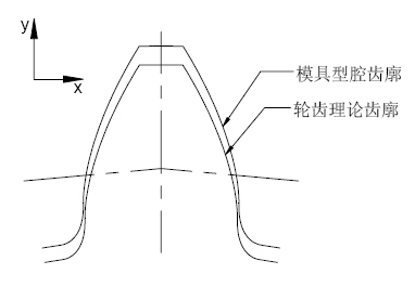
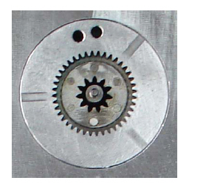
Figure 7 Gear mold type
Faced with this technical problem, it is difficult to receive good results by designing the mold cavity by using the isotropic proportional shrinkage method of general plastic parts. According to the practice test of our company for many years, on the basis of accurately estimating the plastic shrinkage rate, we recommend the variable modulus method for the theoretical design of the gear mold cavity, and then the tooth shape correction to ensure the accuracy and reasonableness of the mold cavity. The variable modulus method considers that: in the various machining processes, the diameter of the base circle, the diameter of the index circle, the diameter of the tip circle and the diameter of the root circle are the same, which are increased or decreased according to a certain ratio, and a simple sleeve. The radial dimension of the barrel parts changes uniformly. For the gear index circle, it is known from the formula d=mz that it is only related to the modulus m and the number of teeth z. For a specific gear, since the number of teeth is constant, the change in the diameter of the index circle during processing can be considered as the modulus changes. This law shows that the space accommodated by the plastic gear mold cavity is an imaginary gear with the same number of teeth and pressure angle and the modulus, and its groove is the tooth shape of the cavity. The modulus of this imaginary gear can be calculated by a method of proportional method, which is: m' = (1 + η%) m. Where m' is the modulus of the mold cavity tooth shape; m is the theoretical modulus of the design gear; η% is the shrinkage of the plastic. The gear obtained by substituting the modulus m' into the corresponding gear calculation formula is the imaginary gear of the mold cavity. Practice has proved that the gear mold cavity designed by variable modulus method can better solve the nonlinear shrinkage problem of the involute profile, as shown in the mold cavity product diagram shown in Fig. 7. 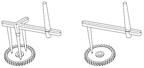
Figure 8 Three points and a little bit of glue
Figure 9 shows the comparison of the flow direction of one point and three points into the fiber 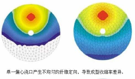
3 exhaust design
Figure 10 tooth surface exhaust 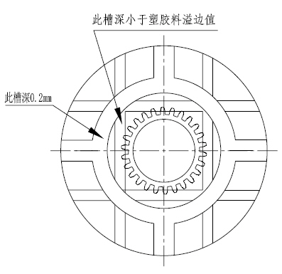
Exhaust is a problem that must be considered in the design of plastic molds. For plastic gear molds, the tooth surface exhaust design is a point that cannot be ignored. Since most of the planes of the gear mold are processed by the grinding machine, the surface-to-surface bonding is better. When filling the glue, it is easy to fill the gap at the last filling place. It is necessary to open the exhaust groove on the tooth surface to eliminate the trapped air. The surface venting opening is as shown in Figure 10.
4 Mold structure In view of the fact that the plastic gear injection molding adopts the dot gate type, the mold structure is mostly three-plate structure, as shown in Fig. 11 is the design of the gear mold and the physical diagram of the gear mold shown in Fig. 12. The working principle of the gear mold is as follows:
When the injection molding operation is completed, the moving part is driven by the injection molding machine to start typing:
The first type of classification: due to the action of the spring 1, the stripping plate and the A plate begin to be classified. Under the action of the crochet of the nozzle, the main channel is fixed on the stripping plate, and the feeding point is broken and separated from the product;
The second classification: after the mold is opened 95mm, under the action of the tie rod group, the stripping plate and the panel begin to separate, and the main channel is separated from the sprue sleeve;
The third classification: the mold continues to open the mold. Under the action of the tie rod group, the A plate and the B plate start to be divided. After the mold is opened to 90 mm, the ejector plate starts to move, and the product is ejected, and the thimble is required during the ejection process. The plate guide column enhances the ejector balance. The ejector plate is reset by the action of the spring 2. A complete set of mold opening and ejection actions is completed.
Figure 11 Plastic gear mold structure 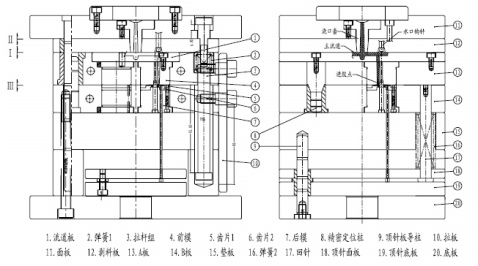
Figure 12 Plastic gear mold 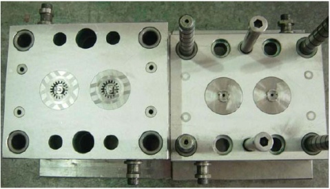
Second, plastic gear mold manufacturing
In the plastic gear molding process, the gear mold is the molding equipment of the plastic gear, which is the key to ensure the accuracy of the plastic gear. The root plastic gear mold can be divided into two parts: the gear cavity and the mold base. Among them, the gear cavity is also called the ring gear, which is the most demanding and accurate part of the whole gear mold processing, and is the top priority of the whole gear mold processing. The machining process of the gear mold is shown in Figure 13.
1 Gear cavity machining Gear cavity machining is the key to the manufacture of the entire plastic gear mold. Since the plastic processing of the plastic gear is a "profiling" processing method, that is, the tooth profile of the cavity is a deformation template of the gear tooth shape. Therefore, the dimensional error and surface roughness of the cavity must be strictly controlled, and there should be no defects such as burrs, eccentricities, and surface scratches. To this end, a strict gear cavity machining process must be established to ensure the accuracy of the cavity fabrication.
There are four main processing methods for gear cavities: wire cutting, EDM, electrodeposition, and beryllium copper casting. These four methods have advantages and disadvantages when machining gear cavities. For involute spur gears, wire cutting is usually used, while for helical gears, EDM is generally used. In addition, the electrode for the use of the EDM gear cavity can also be processed by the wire cutting method. For the helical gear electrode with a smaller helix angle (β≤6°) instead of the worm wheel and the worm, the wire cutting process can still be used. . The ring gear wire cutting process is shown in Figure 14.
2 Formwork processing formwork, also known as mold blank, is an auxiliary forming part of the gear mold. The mold processing process is shown in the machining process of the mold blank in Figure 13. Formwork processing is similar to the processing of common plastic parts injection molds, so this article will not repeat them. The physical diagram of the gear formwork is shown in Figure 12. 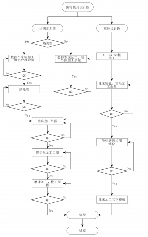
Figure 13 gear mold processing flow chart 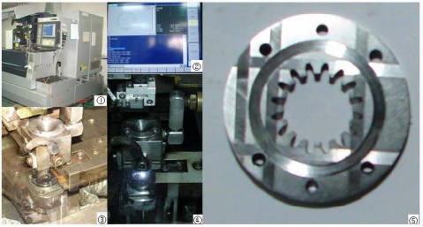
Figure 14 Ring ring cutting process Note: 1 slow wire machine 2 ring gear parameter setting 3 fixed ring gear 4 wire cutter ring 5 wire cut ring gear
For more information, call 18824561887, Peng, Emill: [email protected], QQ. Website: http://. Welcome friends from all walks of life come to visit, guide and negotiate business.
Dongguan Shunjie Gear Co., Ltd.
Http://news.chinawj.com.cn Editor: (Hardware Business Network Information Center) http://news.chinawj.com.cn