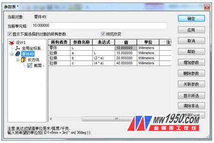
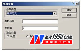
The parametric design method in 3D CAD is to quantify the quantitative information in the model and make it an arbitrary adjustment parameter. Then assign different values ​​to the parameters to get the part models of different sizes and shapes. Parametric design can be generated by using expressions in the CAXA entity design to establish associations with expressions and then linking the parameters to the shape bounding box size. Let's first introduce the basics of parameterization and serialization: parameter tables, parameter types, and expressions. 1. Parameter list The “Parameter Table†shows all the parameters, and you can also generate and customize some parameters to modify the part design more effectively, while meeting specific needs. The parameter table corresponds to different current objects and can be used to design environments, assemblies, parts, shapes, or 2D sketch outlines. In different selection states, such as design environment, assembly, parts, pixels or 2D sketches, right click the mouse to pop up the right-click menu corresponding to the status, select "Parameter" from it, the "Parameter Table" dialog box will be displayed on the screen. . The "current object" at the top of the "Parameter Table" dialog box displays the name of the selected object corresponding to the parameter table. If you access the Parameter Table from the design environment, the name is empty. Below the component name, the Current Cell field displays the currently selected cell content. The next option is "Show all parameters of the object selected below". This option is not selected by default. At this time, the "Parameter Table" only displays the current parameters that appear in the access status of the table. When this option is selected, the parameter table expands, in addition to displaying the current parameters of the state, it also displays all the parameters of the subordinate components contained in the current object. For example, selecting this option in the design environment state displays the parameters for each assembly, part, tile, and sketch in the design environment. Selecting this option in the part state displays the parameters for the selected part and all its tiles and sketches. The following columns on the "Parameter Table" show the following information for all current parameters: Path: This column shows the path where this parameter is located. This path is displayed in the system name. Owner Type: This column displays the type of owner of this parameter, which can be the type of design environment, assembly, part, or tile. Parameter Name: This column shows the name of the current parameter. Expression: This column displays the expression assigned to the current parameter. It must be noted that all expressions are assigned in system units (eg, meters, radians, and kilograms) unless otherwise stated. A detailed description of the expressions will be given later. Value: This column displays the value of the current parameter. Unit: This column shows the unit used by the current parameter. Note: This column shows supplementary notes/notes to the current parameters. On the right side of the "Parameter Table" are the following options: OK: Select this option to confirm the changes made to the parameter table and return to the design environment. Apply: Select this option to confirm the changes made to the parameter table and preview the modifications in the design environment without exiting. Cancel: After modifying the "Parameter Table", if you select this option, the modification result will not be executed. Select this option to cancel any modifications made to the Parameter Table since the last Apply action and return to the design environment. Add parameter: Select this option to enter the Add Parameter dialog box, as shown in Figure 8-2, to generate a new parameter. The parameters generated with this option are called "user-defined" parameters. Delete parameters: Highlight the parameters that need to be removed from the parameter list, then select this option to delete. Figure 8-2 Add Parameter dialog box The contents of the "Add Parameter" dialog box are as shown: Parameter Name: Enter the corresponding name for the new parameter. Parameter value: Enter the corresponding value for the new parameter. Value type: Select the appropriate parameter type from the following options: Length: Select this option to specify a linear parameter type. Angle: Select this option to specify an angle parameter type. Scale factor: Select this option to specify a unitless type, only as a parameter type for the scale factor, such as the number of holes. 2. Parameter type There are two types of parameters in the CAXA entity design: (1) User-defined: These parameters are generated directly by user definition. User-defined parameters are generated by using the Add Parameter option in the Parameter Tables dialog box. These parameters are independent of any 2D sketch geometry or 3D shape/part during the build process. User-defined parameters must be manually connected to be related to the entity. (2) System-defined type: The parameters automatically generated by the CAXA entity design when adding smart dimensions, dimensional constraints in 2D sketches, and generating arrays. The CAXA solid design automatically generates system-defined parameters when generating locked smart dimensions on 3D pixels/parts, generating constraint sizes on 2D sketches, generating constrained assembly sizes in the design environment, and generating various arrays. When a system-defined parameter is generated, it automatically associates with the corresponding size. Modifications made when editing the values ​​of system-defined parameters are automatically applied to the corresponding dimensions. 3. Expression An expression can customize its existing parameters or associate one parameter to another. Expressions can be written using standard mathematical notation: *, /, +, and -. The CAXA entity design provides an internal library of functions to support ï°, absolute values, sine, cosine, and more. For more information, please refer to the CAXA Entity Design Help. The basics of parametric design are introduced here, and we will use a series of examples to illustrate the application of parameterization in design. Brass Flange Ball Valves,Brass Flanged Gate Valve,2 Brass Ball Valves,Brass Ball Valve 3/4 NINGBO RIDE SPORT EQUIPMENTS CO.,LTD. , https://www.assur-valve.com
