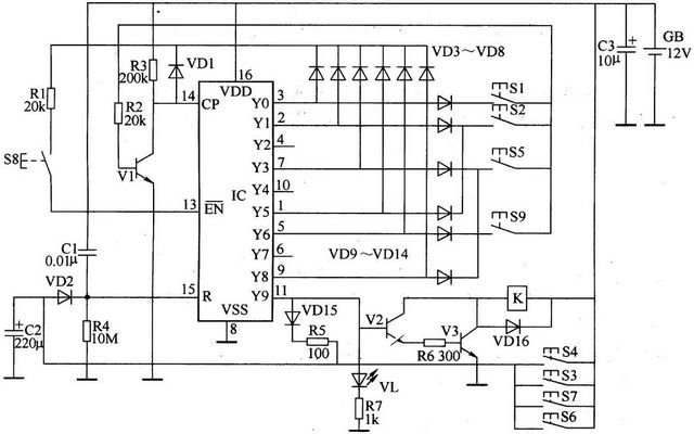
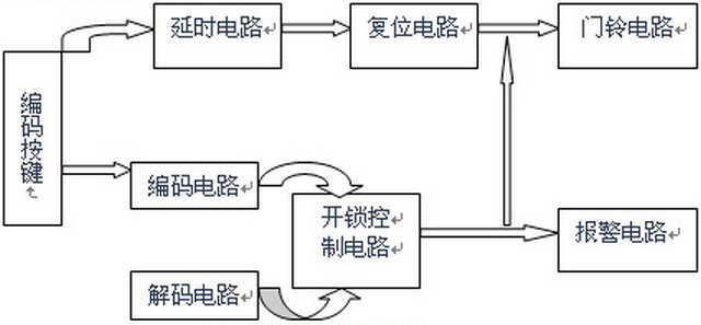
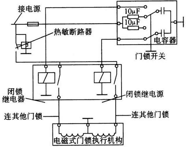
What is the principle of electronic lock? How is the electronic lock working principle? The wide range of electronic locks includes the electronic lock principle of electric vehicles, the principle of automotive electronic locks, and the working principle of electronic locks. This article focuses on the design principle of the electronic lock and introduces the entire workflow through the electronic lock schematic. With more and more applications of electronic locks, the role of electronic locks in daily life is becoming more and more important. Let's take a look at the scientific content of this article. To understand how electronic locks work, you first need to know the definition and concepts of electronic locks and learn what electronic locks are. The electronic lock is an upgrade of the traditional mechanical lock. Based on the electronic lock of the circuit control chip, the circuit controls the closing of the mechanical switch to control the opening and closing of the lock. The smart lock is based on the electronic locks based on the upgrade, integrated electronic technology, integrated circuit design, a large number of electronic components, with a new identification technology (biometrics, sensor identification, password recognition, etc.) in one intelligent electronic lock, The electronic lock generally takes the 51 series single-chip computer (AT89051) as the core part and is equipped with the corresponding hardware circuit to complete the setting, storage, identification and display of the password, drive the electromagnetic actuator and detect its driving current value, and receive the alarm sent by the sensor. Signal, send data and other functions. Take the common electronic code lock as an example, the SCM receives the input digital code and matches it with the code stored in the EEPROM. If the code is completely correct, the SCM chip controls the electromagnetic actuator to unlock; if the code is wrong, the user is allowed to input again. The password limits the number of input errors; if the number of attempts beyond the limit is incorrect, the microcontroller will alert the intelligent monitor via the communication circuit. The single-chip microcomputer sends each time the unlocking operation and the drive current value of the electromagnetic actuator to the intelligent monitor as status information, and simultaneously sends the alarm information received from the sensor interface to the intelligent monitor as an analysis reference. The input control circuit is composed of password buttons S1, S2, S5, S8, S9, diodes VD3-VD14, resistor R1, and the like. Counting/distributor circuit consists of IC and transistor Vl, resistor R2, R3, diode VDl. The reset circuit consists of capacitors Cl, C2, diodes VD2, VDl5, resistors R4, R5 and buttons S3, S4, S6, S7. The control circuit consists of transistors V2, V3, light-emitting diodes VL, resistors R6, R7, relays (or electrically controlled locks) K and diodes VDl6. After the power is turned on, the +l2V voltage is provided by Cl as the R terminal (15 feet) of the IC to provide a reset high level, so that the IC is reset, and the YO terminal (3 feet) outputs a high level, and the rest of the output terminals are low power. level. When S1 is pressed, the high level of YO is added to the base of V1 by VD9, S1, and R2 to make V1 saturate. After releasing, Vl is cut off and a trigger pulse is generated at the CP end of the IC. The IC starts. Counting, its Yl end (2 feet) exports the high level, and YO end and the other each output end is the low level. Press S2 again, the high level of IC's Yl end makes Vl turn on again, after releasing S2, Vl ends, IC counts the second pulse, its Y2 end (4 feet) outputs the high level, Yl end and The rest of the outputs are low. When S8 is pressed, +l2V voltage forms a closed loop to ground via R3, VDl, Rl, and S8. After releasing S, a trigger pulse is also generated at the CP end of the IC, making the IC count the third pulse, and its Y3 end (7 feet) Output high level. When S5 is pressed, the high level of Y3 is turned on by VD11, S5, and R2. When S5 is released, V1 is cut off. The IC counts the 4th pulse, and Y4 (10 pins) outputs the high level. Press S8 again, the Y5 terminal of lC (l pin) goes high again; press S2 to make Y6 of the IC go high; press S9 to make Y7 of lC high Level; press S8 to make Y8 of IC become high level; press S5 to make Yg of IC output high level, then VL turns on, V2 and V3 conduct, relay (or electricity) Control lock) K action, open the lock. At the same time, the high level of Y9 is also charged to C2 via VD15 and R5. When C2 is full (after a few seconds), VD2 is turned on, and the IC is reset by adding a high pulse to pin 15 and the YO output is high. Electric power, V2 and V3 deadline, K release, VL extinguished. The circuit's unlock password is 128582985. Change the password of each button as needed to change the password. If you do not know the password and press the buttons S3, S4, S6, and S7 by mistake, the IC is forced to reset. The YO pin outputs a high level and cannot be unlocked. Component Selection: Rl-R7 use 1/4W carbon film resistor or metal film resistor. Cl chooses monolithic capacitors or polyester capacitors; C2 and C3 use aluminum electrolytic capacitors with a voltage rating of 16V. VDl-VDl5 selects lN4148 silicon switch diode for use; VDl6 selects 1N4007 silicon rectifier diode for use. Vl and V2 select S9013 or Model 3DG9013 silicon NPN transistor for use; V3 selects Model N80 transistor such as C8050 or S8050 for use. The IC uses the CD4017 or CC4017 type decimal count/distributor IC. S1-S9 all use dynamic (normally open) type micro-buttons. K chooses l2V relay or electric control lock. The unlocking process (taking a keyboard-type password lock as an example): starting with the power supply, the program is initialized, and then the unlocking or setting password is selected. The keyboard scanning is required during the unlocking process, the password is correct, the unlocking is successful, and the password error is 3 error alarms. To change the password, enter the old password first. After the password is correct, set the new password. If the alarm is incorrect, you need to confirm the new password twice. After the confirmation, the password is successfully modified. Otherwise, the final return is completed. 1, Built-in motor electronic lock: The lock body has a drive motor installed inside, brush cartoon electric, drive motor rotation to eject / retract lock tongue / lock point. 2, part of the plug-in electric control lock: the lock body does not have a motor device, replaced by an electromagnetic structure, the state of the card is not swiped, the door lock handle and the drive shaft is disconnected, turning the handle can not open the door, swipe, generate electricity With magnetic induction, the connecting rod is pushed to the position where it is connected to the drive shaft. At this time, the rotating handle and the drive shaft are connected to open the door lock. A large part of electronic locks are smart locks, including electronic code locks, fingerprint locks, Bluetooth locks, and so on. Widely used in automobiles, electric vehicles, shared bicycles, access control, home door locks and other fields. The above is a smart lock Chinese network Xiaobian finishing electronic lock principle and electronic locks work principle diagram, more lock knowledge, please pay attention to the site related to the introduction!
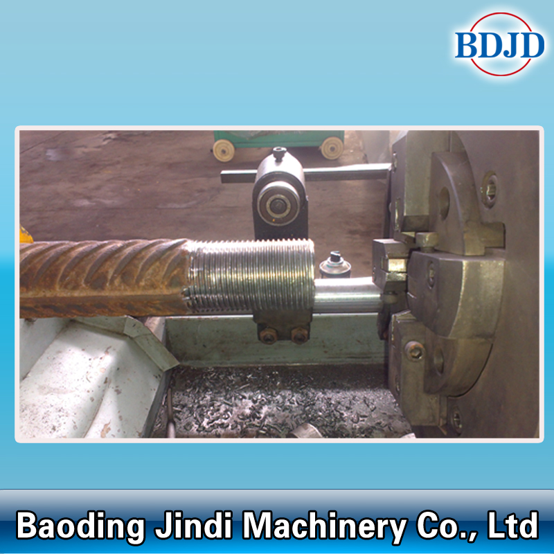
JBG Series Rebar Thread Rolling Machine designed for processing parallel threads for rebar mechanical connection in construction. It can process HRB335, HRB400, HRB500 hot rolled ribbed reinforced bar.
JBG-40CI Rebar Rib-peeling and parallel Threading Rolling Machine adds the screw pitch angle mechanism. It is easy to operate, and processed thread is more precise, with small conical degree and surface is more smooth.
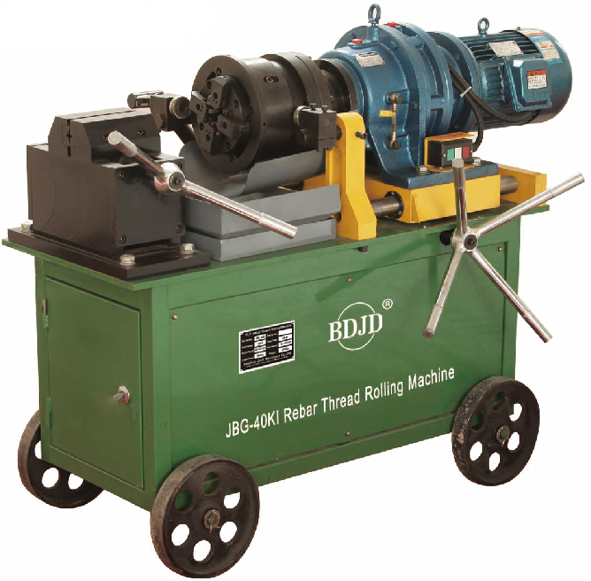
JBG-40K uses larger machine rack which makes machine more stable. It adopts famous brand reducer, the machine performance is more superior. It also adopts patented design which eliminates the problem that the rebar thread often becomes bigger, and that the stripping head open automatically.
JBG-40KI rebar rib-peeling and parallel thread rolling machine adds the screw pitch angle mechanism. It is easier to operate, the thread precision is more higher, the conical degree is more smaller, and the thread surface is more smooth.
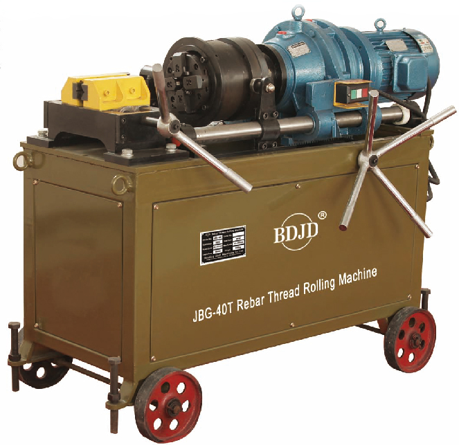
JBG-40T has the unique characteristic of only need starting one time when processing left-handed thread, and it can finish rebar rib peeling and threading rolling continuously. With wxtended plate thread processing length could reach 100mm. It is especially fit for long rebar thread process in bridge and tunnel.
JBG-40F adds screw pitch angle mechanism, it is eaiser to operate, save labor and the effective thread length maximum can be 200mm/300mm.
JBG-50 Rebar Thread Rolling Machine is especially fit for long rebar thread processing and large diameter rebar in bridge and tunnel. At the same time, it makes up the shortall that manufacturer in the same industry can not process rebar diameter 12mm and 50mm.
JBG Series Rebar Thread Rolling Machine JBG Series Rebar Thread Rolling Machine,Rebar Thread Rolling Machine,Threading Rolling Machine,Electric Rebar Thread Rolling Machine BAODING JINDI MACHINERY CO., LTD , https://www.rebarconnector.com